
الدليل الفني للطرق والكباري
إظهار الرسائل ذات التسميات هندسة الجسور. إظهار كافة الرسائل
إظهار الرسائل ذات التسميات هندسة الجسور. إظهار كافة الرسائل
الكود الامريكي للجسور على الطرق السريعة AASHTO: Standard Specifications for Highway Bridges
The Design of Prestressed Concrete Bridges تصميم الكباري البيتونية مسبقة الاجهاد
The Design of Prestressed Concrete Bridges

The book is organised as follows:
The meaning and nature of design as opposed to analysis is discussed in
Chapter 1.
Chapter 2 is an introduction to some basic structural engineering concepts and
to the specialised vocabulary used in the book. It is for the convenience of nonengineers.
Chapter 3 is an introduction to reinforced concrete as this is necessary to understand
the later chapters.
Chapters 4, 5 and 6 explain the principles of prestressing.
Chapter 7 is concerned with the articulation of bridges and the design of substructure.
Chapter 8 describes the logic that underpins the design of decks for girder bridges,
and gives benchmarks for the material quantities that should be achieved.
Chapter 9 analyses the function of each of the components of a bridge deck.
Chapters 10, 11, 12 and 13 describe the different types of bridge deck.
Chapters 14 and 15 are devoted to the methods of construction of bridge decks.
Chapter 16 is a synthesis of the preceding chapters, describing how the scale
of a bridge project infl uences the choice of the type of deck and its method of
construction.
Finally, Chapters 17 and 18 deal with arches and suspended decks which follow a
different logic from girder decks.
Cross-referencing to sections elsewhere in the text is by section numbers shown in
italics.
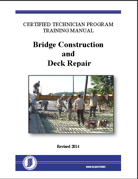
Bridge Construction and Deck Repair تنفيذ الكباري وصيانة اجزائها العلوية
Bridge Construction and Deck Repair
تحميل الكتاب
This guide explains the following topics: Basic Bridge Terms, Bridge Plans, Construction Controls and Layout, Structure Excavation, Foundation Piling, Forms, Falsework, and Reinforcement, Concrete Placement, Bearings and Structural Members, Bridge Decks, Bridge Deck Repair.
Author(s): State of Indiana
Design of Reinforced Concrete Bridges تصميم الكباري (الجسور ) البيتونية المسلحة (الخرسانية)
Design of Reinforced Concrete Bridges
تصميم الكباري (الجسور ) البيتونية المسلحة (الخرسانية)
ملخص تنفيذي
يتكون تقرير المشروع بأكمله من جزأين. يقدم القسم الأول ، الجزء أ ، وصفًا نوعيًا كاملاً لعملية تصميم الجسور الخرسانية النموذجية سابقة الإجهاد. يوفر الجزء الثاني ، الجزء ب ، تصميمًا تفصيليًا كميًا فعليًا لجسر خرساني سابق الإجهاد فيما يتعلق بثلاثة معايير تصميم مختلفة.

Executive Summary
The entire project report consists of two parts. The first section, Part A, presents a complete qualitative description of typical prestressed concrete bridge design process. The second part, Part B, provides an actual quantitative detailed design a prestressed concrete bridge with respect to three different design standards.
In particular, the first part of the report reviews the failure of four different bridges in the past with additional emphasis on the De La Concorde Overpass in Laval, Quebec. Various types of bridges in terms of materials used, cross-section shape and structural type were investigated with their application as well as the advantages and disadvantages. In addition, the predominant differences of the Canadian Highway and Bridge Design Code CSA S6-14 and CSA S6-66, as well as AASHTO LRFD 2014 were discussed. After that, the actual design process of a prestressed concrete bridge was demonstrated, which started with identifying the required design input. Then, several feasible conceptual design options may be proposed by design teams. Moreover, the purpose and significance of structural analysis is discussed in depth, and five different typical analysis software were introduced in this section. Upon the completion of structural analysis, the procedure of detailed structure design and durability design were identified, which included the choice of materials and dimensions of individual specimens as well as the detailed design of any reinforcement profile. Last but not least, the potential construction issues as well as the plant life management and aging management program were discussed and presented at the end of the Part A.
On the other hand, the second part of this report presents a detailed structural design of a prestressed concrete bridge with a span of 25 meters based on three different design standards. It started off with a problem statement that defines the scope of the entire design. The concept of influence line is used to analyze the moving track load, which is then combined with other live loads and dead loads to come up with the entire shear force and bending moment envelope along the bridge. Once all the design loads had been determined, detailed computational designs were performed for both prestressed concrete girders and reinforced concrete decks with respect to three different bridge design standards. Aside from the structural designs, the durability concrete mix design is also provided as part of the bridge design, which takes the environmental conditions into consideration. Finally, the detailed drawings of the bridge are attached at the end of the entire report.
This design report summarized the knowledge and skills that our design team has gained from this course of Capstone Design Project as well as the rest of undergraduate program curriculum. It also provides strong insight on the connections and differences between different design standards, and the impacts these differences could make to the designs. Furthermore, the past failures included in this report has taught us that not only theoretical knowledge, but also the responsibilities of being a future structural engineer. The outlined step-by-step design procedure in this design report may be used for future reference on similar design projects.

Reinforced Concrete Bridges
Superstructure Design

"Reinforced Concrete Bridges."
Bridge Engineering Handbook.
9.1 Introduction
9.2 Materials
Concrete • Steel Reinforcement
9.3 Bridge Types
Slab Bridges • T-Beam Bridges • Box-Girder Bridges
9.4 Design Considerations
Basic Design Theory • Design Limit States • Flexural
Strength • Shear Strength • Skewed Concrete
Bridges • Design Information • Details of
Reinforcement
9.5 Design Examples
Solid Slab Bridge Design • Box-Girder Bridge Design
Basic Components and Parts of Bridge Structures المكونات والاجزاء الرئيسية للكباري (الجسور)
Basic Components and
Parts of Bridge Structures
The
bridge structure consists of the following components:
- Superstructure
or decking component
- Bearings
- Substructure Components

Fig:
Semi-Through Section of a Concrete Slab Road Bridge
Superstructure Components
of Bridges
The
superstructure of the bridge structure consists of deck slab, girder, truss
etc. These components vary based on the type of bridge (whether concrete or
steel or composite). Superstructure of the bridge bears the load passing over
it. This helps in transmitting the forces formed by the loads to the below
substructures.
Decks
The
decking is considered as the road or the rail surface of the bridge. The decks
are supported by the girders or the huge beams that is in turn supported by the
piers. The whole arrangement is supported with a deep foundation mainly piles
and cap arrangement.

Bearings in Bridges
The loads
received by the decks are properly and safely transmitted to the substructure
with the help of bearings. These are components of bridge that enables even
distribution of load on the substructure material. This transmission is very
essential in situations where the substructure is not designed to take the load
action directly.

The
bearings in bridges allows the longitudinal movement of the girders. This
movement is created due to the forces acting on the longitudinal direction. The
forces due to the moving loads and the variation in temperature are the main
causes for longitudinal forces.
The
selection of bearing is dependent on certain parameters, which are: Loads
acting, the geometry, the extent of maintenance, the clearance available, the
displacement, rotation and deflection policy, availability, preference of the
designer, the construction tolerances, and the cost criteria.
For the
bridge design, all the above-mentioned aspect is considered for the design and
the choice of bearings. The designer must consider the bearing arrangement in
the bridge construction as a separate system.
In most
of construction practice, the bearing is selected or the decision for bearing
is done in the last moment. This results in increase of maintenance in the
future, which must be avoided.
Substructure Components
of Bridges
The
components involved in substructure of bridges are:
- Piers
- Abutments
- Wing
Walls and the Returns
- Foundation
Piers
The piers
are vertical structures used to support deck or the bearings provided for load
transmission to underground soil through foundation. These structures serve as
supports for the bridge spans at intermediate points.
The pier structure has mainly two functions:
- Load
transmission to the Foundation
- Resistance to the horizontal
forces
Most of
the cases, piers are designed to resist the vertical loads alone. In areas
which lie in the seismic zone, it is recommended to design the pier for lateral
loads also.
Most of
the piers are constructed using concrete. Steel for the construction of pier is
used in very few cases till now. Use of composite columns i.e. steel columns
filled with concrete is used as new technology of pier construction.
The pier is a vertical member that resist the forces by means of
shear mechanism. These forces are mainly lateral forces. The pier that consist
of multiple columns are called as bent.

Types of Piers in Bridge
Construction
There are
different types of piers based on the structural connectivity, the shape of the
section and the framing configuration.
- Based on the structural
connectivity, the pier can be classified as monolithic or cantilevered.
- Based on the shape of the section
pier can be classified as solid or hollow, hexagonal, round or
octagonal or rectangular.
- Based on the framing configuration
the pier can be classified as single or multiple column bent, hammerhead
or pier wall type.
Abutments
Abutments
are vertical structures used to retain the earth behind the structure. The dead
and the live loads from the bridge superstructure is supported by the bridge
abutments.

The
abutments are also subjected to lateral pressures mainly from the approach
embankment. The design loads on the abutment is mainly dependent on the:
- Type
of abutment selected
- The sequence of construction
The
figure below shows the primary functions carried out by an abutment.

Fig:
Abutments in Bridge Construction- Primary Functions
As seen
from the above figure, the abutments have the design requirements similar to
retaining walls as well as in pier construction. The abutments are primarily designed
to resists the overturning and sliding. More focus is on the stability of the
whole system.
The
special care has to be provided for the foundations of abutments. The abutment
foundation must overcome the problems of differential settlement and excessive
movements caused due to lateral forces or loads.
The below
figure shows the components of abutments.

Fig:
Abutments Components
Wing Walls and Returns
Structures
constructed as an extension of the abutments to retain the earth present in the
approach bank are called wing walls. This portion will otherwise have a natural
angle of repose. These are retaining walls constructed adjacent to the
abutments. This wall can be constructed either integrally or independent with
the abutment wall.
The rear
of the wall must consider three design loads while designing. This includes:
- The
earth pressure from the backfill
- The
surcharge from the live loads or the compacting plant
- The hydraulic loads from the
saturated soil conditions
The
stability of the wing wall is mainly based on its resistance against the active
earth pressures. The structural elements of the bridges are hereby designed and
constructed to resist the earth pressures at rest.

Parapets and Handrails/
Guard Rails or Curbs
These
components of bridges are not of structural importance, but provided for the
safety concerns. These are provided above the decks. This will help in
prevention of the vehicle from falling off the bridge into the water body below
or as a means for the separation of traffic streams.

Foundation of Bridges
Foundation
are structures constructed to transmit the load from the piers, abutments, wing
walls and the returns evenly on the strata.

The
foundation provided for bridge structures are deep in sufficient manner to
avoid scouring due to the water movement or to reduce the chances of undermining.
Steel Bridges الجسور (الكباري) المعدنية
Steel Bridges

This book covers the design of steel bridges in general with emphasis on bridge systems commonly used to cover short and moderate spans, namely plate girder bridges, box girder bridges, and truss bridges. The book is intended for senior year college students and practicing bridge engineers. Topics covered includes: Types Of Bridges, Materials For Bridge Construction, Design Loads On Bridges, Design Considerations, Bridge Floors, Plate Girder Bridges, Composite Plate Girder Bridges, Box Girder Bridges, Truss Bridges.
Author(s): Metwally Abu-hamd


الجسور (الكباري) المعدنية
يغطي هذا الكتاب تصميم الجسور الفولاذية بشكل عام مع التركيز على أنظمة الجسور التي يشيع استخدامها لتغطية المسافات القصيرة والمتوسطة ، الكتاب مخصص لطلاب السنة الجامعية الأولى ومهندسي الجسور الممارسين. تشمل الموضوعات التي يتم تناولها: أنواع الجسور ، مواد بناء الجسور ، أحمال التصميم على الجسور ، اعتبارات التصميم ، وغيرها من المواضيع
المؤلف / المؤلفون: متولي ابو حمد
تحميل الكتاب 👆
الكود الاوروبي لتصميم المنشات المعدنية والهياكل المختلطة
الكود الاوروبي لتصميم المنشات المعدنية والهياكل المختلطة
دليل المصممين إلى EN 1994-2
EUROCODE 4: تصميم المنشات المعدنية والمنشات المختلط
الجزء 2: المبادئ العامة ومبادئ تصميم الجسور والكباري
للتحميل


DONLOAD


الكود الاوروبي لتصميم الجسور والكباري الخرسانية
EUROCODE : DESIGN OF CONRETE STRUCRES
PART 2 CONCRATE BRIDGES

رابط التحميل

للتحميل


تصنيف الجسور (الكباري) والعناصر المكونة لها
تصنيف الكباري والعناصر المكونة لها

محاضرة للدكتور ساطع بدوي الاستاذ في جامعة دمشق
تهدف لتعريف المهندسين الالغير اختصاصيين في مجار الكباري بها واهم مكوناتها كي يتمكنوا من العمل في مجال المعاينة وتحديدي الاضرار والاصلاح
للتحميل عبر الرابط
https://www.file-upload.com / zo70ymktc1ru
مراحل تنفيذ الكباري الخرسانية (الجسورالبيتونية المسلحة ) بالتفصيل بالصور
مراحل تنفيذ الكباري الخرسانية (الجسورالبيتونية المسلحة ) بالتفصيل بالصور
ملف مصور لمراحل تنفيذ الكباري من الالف الى الياء
للاطلاع على كامل الملف عبر الرابط


تحميل الملف كاملا اضغط هنا
الاشتراك في:
الرسائل (Atom)